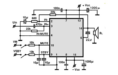


The amplified output through Q2 can be obtained over the 1kΩ resistor. Additionally, it offers additional amplification. Transistor Q2 is designed like fixed bias by using a 100kΩ resistor. The capacitor eliminates DC voltages because of the biasing of Q1. The output of Q1 reaches at the collector (throughout 1kΩ resistor), that is the input to the transistor Q2 through a 0.1♟ capacitor. This resistor offers negative feedback for the transistor Q1. This really is achieved through 100kΩ resistance. Transistor Q1 is set up as collector to base biasing function. The output of condenser mic is actually combined by using a coupling capacitor of 10♟, the objective of this capacitor would be to eliminate DC material in the audio transmission.Ī 1kΩ resistor is employed to offer the necessary biasing to the condenser microphone. The increased output is acquired over the loudspeaker. These electrical impulses tend to be far too weak it is therefore amplified through the amplifier unit. The two transistor MIC amplifier circuit is isolated into three sections: Condenser mic, audio amplifier and loudspeaker.Ĭondenser microphone is really a type of capacitive sound sensor (audio transducer) that will switch the sound (audio) signal directly into electrical impulses. Speaker (8Ω, ½ Watt) Working of amplifier Transistors any small signal type such BC547 or 2N3053 This circuit is suitable for inexpensive sound amplification requirements in electronics for example pre-amplifier for FM audio receivers. Source: If you need exactly 6 you can play a round with the resistance on the input.You are able to build this circuit using a minimal price. Source: For splitting the signal you can use resistors for basic splitting. When you said after connecting stby to vcc that is ambiguous since there is a point labelled st by on the diagram top left but pin 7 of the ic is also called st by. In this circuit we can use 10 transistors. Source: ĥ are ttc5200 and another 5 are tta1943. If you need exactly 6 you can play a round with the resistance on the input. Source: If you need exactly 6 you can play a round with the resistance on the input. Using transistors mosfet ic on a lot types. At90s8535 tda7318 and lm3886 have been realized with digital amp system led indicator signal input selection can be made unfortunately explanations could. This is a 4 1 amplifier schematic diagram this diagram we can use as a car amplifier or also we can use in the home this is home theater amplifier also.įor splitting the signal you can use resistors for basic splitting. Many power amplifier circuit diagram with pcb layout. A wide variety of tda7379 amplifier circuit options are available to you such as 3 2 1 2 2 0 and 1. This is a 4 1 amplifier schematic diagram this diagram we can use as a car amplifier or also we can use in the home this is home theater amplifier also. Tda7379 Amp In Double Bridge Config Draws Correct Quiescent Current But Gives No Sound Electrical Engineering Stack Exchange from


 0 kommentar(er)
